MIPS Processor
I wrote a 5-stage pipelined MIPS processor as part of a computer architecture class at CMU. It includes forwarding, branch prediction, exception handling, user and kernel modes, virtual memory, and a TLB. I also wrote a small kernel in assembly supporting system calls, exception handling, and TLB management. The full source can be found on GitHub.
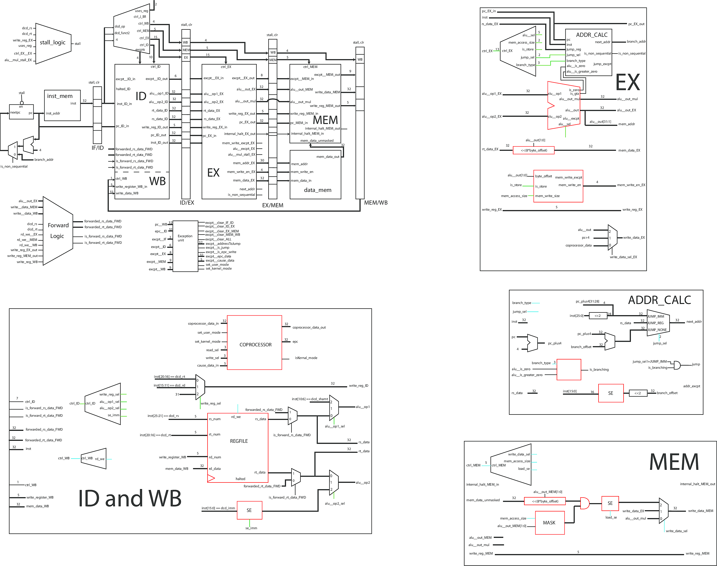
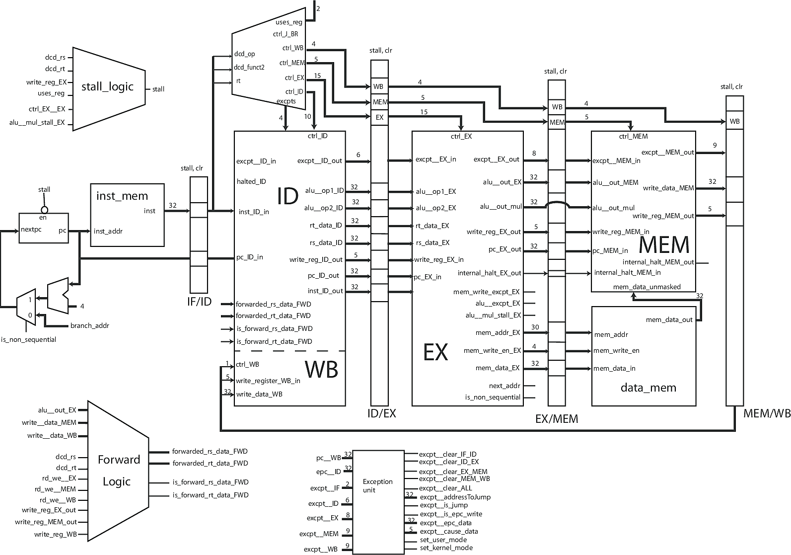
A pipelined 5 stage RISC processor (like MIPS) has a Fetch, Decode, Execute, Memory, and Writeback stage. Each instruction goes through each stage, and at any time there are at most 5 instructions being executed at once (one per stage). Below is a high level schematic of the processor. Complex elements have been separated and I elaborate on their functionality below. A full resolution schematic is also available.
MIPS Core
The MIPS core (source) is the top-level module where everything is wired together. It instantiates the pipeline registers, which are the long, narrow boxes. These allow the processor to work on multiple instructions simultaneously. Between the registers are the different stages, Fetch (inst_mem), Decode (ID), Execute (EX), Memory (MEM), and Writeback (WB). The core keeps track of one of the most important states in any processor, the program counter, which is the memory address of the next instruction.
Forward and Stall Logic
Pipelining enables higher clock frequencies, by creating shorter critical paths, and it also allows for multiple instructions to be computed simultaneously. Unsurprisingly, these advantages come with a trade-off. You need additional logic to deal with corner cases. The most common issue is what is called a data hazard. This occurs when an instruction has been executed, but has yet to be written back to the register file, and the current instruction needs the result of that calculation. This is when forwarding comes in. This module (source) simply takes the outputs of the EX, MEM, and WB stages, and replaces incorrect reads from the register file with valid values.
Sometimes, data hazards are impossible to fix with forwarding. There are times when the data isn't yet available, and the processor must wait in order to continue. For example, this would happen when an instruction reads from memory, and a subsequent instruction needs that value from memory. These events are detected with the stall module (source). The stall module places NOP (No Operation) instructions into the stages that must wait, until the hazard is resolved.
Exception Unit
Exceptions happen in a processor for a variety of reasons. Something can go wrong (like an overflow or invalid memory read), you can have a cache miss, or you may want to implement privileged system calls to distinguish user and kernel modes. The exception unit (source) takes care of these situations. It reads exceptions from every stage and outputs controls that will set the processor into the correct state when an exception occurs. This includes nullifying the misbehaving instruction and any later instructions, jumping to the memory address of the exception handler (which is written in software), and returning control to the original program once the exception is resolved. This module does not store any state information, instead controlling the coprocessor in the ID stage, which stores the relevant addresses and status codes.
Instruction Decode and Writeback Stage
Although Decode and Writeback are two different stages in the pipeline, they share one of the most important parts of the processor, the register file, so they share the same module (source). The register file is an array of registers that holds the result of computations and reads from RAM. It is the fastest form of memory in a computer.
The ID stage is responsible for decoding an instruction into control signals that determine what the rest of the processor does. If an ADD instruction is decoded, this stage reads the two values to be added from the register file, and lets the remaining stages know how to handle the operands.
The WB stage is the simplest stage. It has an enable line, a value to write, and the address to write it to. It takes these inputs and writes the result into the correct register in the register file.
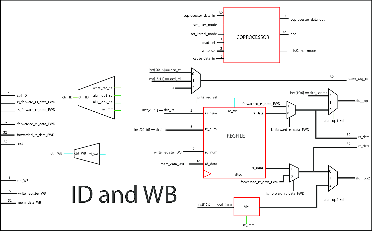
Decoder
The instruction decoding logic has its own module (source), which is instantiated in the MIPS core. However, it is still considered part of the ID stage (it is the large demultiplexer above the ID stage). This module takes an instruction and determines what each stage should do, by sending control signals through the pipeline registers. This is where the magical translation between assembly language and physical signals occurs.
Execute Stage
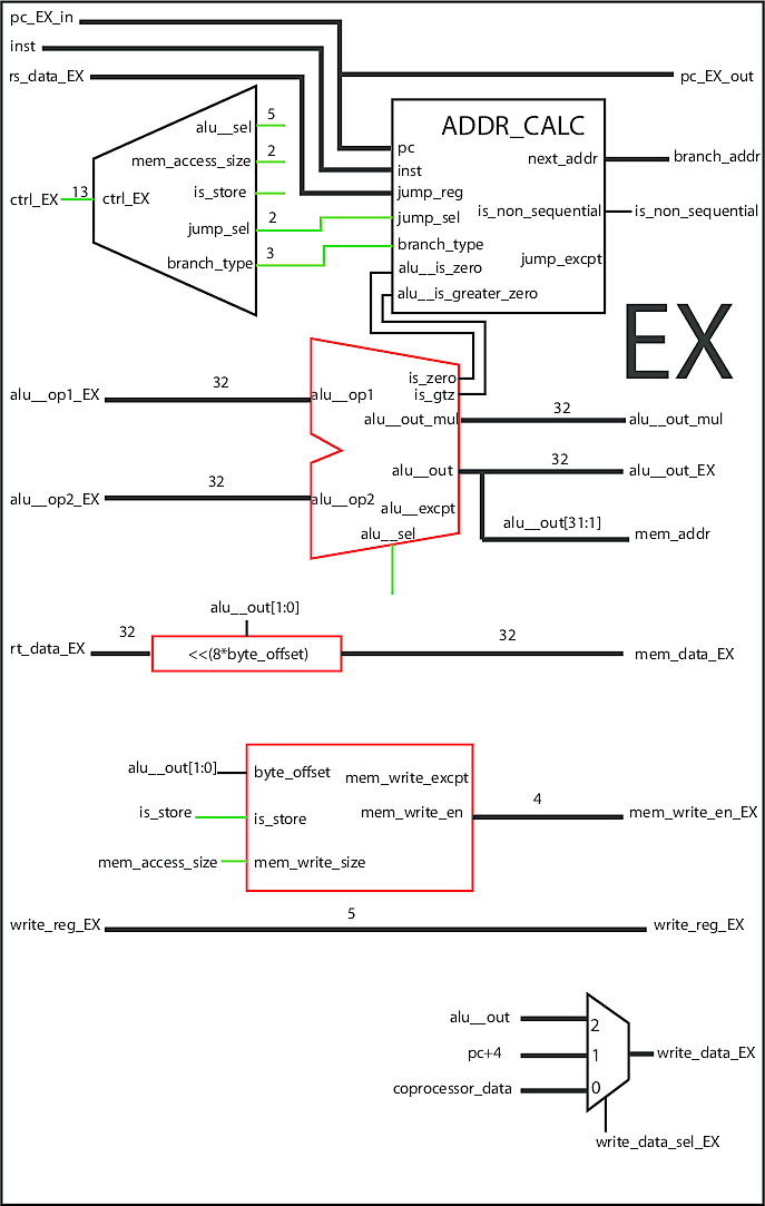
Instructions are calculated in the execute stage (source). If it's a simple arithmetic operation, then the result is computed. If it's a memory operation like a read or write, then the offsets and appropriate signals for the memory stage are calculated. This stage also determines if the next instruction is sequential or a branch, and calculates the next value of the program counter accordingly.
ALU
The ALU (Arithmetic Logic Unit) is the core block of the processor, doing all mathematical and logical operations. It is contained in the execute stage. An ALU takes 3 main inputs - two operands and a select line that is equivalent to an operator. The bulk of this logic is a case statement based on the select line, which returns the result of the desired operation.
For multiply and divide operations, we outsource the work to a pipelined multiplier coprocessor, which can perform these more complicated operations within one execute clock cycle. The ALU also supports some operations to help determine the next program address (with help from the address calculator).
////
//// mips_ALU: Performs all arithmetic and logical operations
////
//// out             (output) - Final result
//// is_zero         (output) - Outputs if the result of a subtraction is 0 (also used in branches)
//// is_greater_zero (output) - Outputs if the operand is > 0. However, only used in branches
//// excpt           (output) - Asserted if the ALU has an excpetion
//// op1             (input)  - Operand modified by the operation
//// op2             (input)  - Operand used (in arithmetic ops) to modify in1
//// sel             (input)  - Selects which operation is to be performed

module mips_ALU(// Outputs
                alu__out, alu__out_mul, alu__is_zero, alu__is_greater_zero, alu__excpt, alu__mul_stall,

                // Inputs
                alu__op1, alu__op2, alu__sel, clk, rst_b);

  output reg [31:0] alu__out;
  output     [31:0] alu__out_mul;         // This is the output of the coprocessor
  output reg        alu__is_zero;         // Only valid for SUB instructions
  output reg        alu__is_greater_zero; // Only valid for branch ALU instructions
  output reg        alu__excpt;           // Assert if we overflow on signed instructions
  output            alu__mul_stall;

  input  [31:0]     alu__op1, alu__op2;
  input  [4:0]      alu__sel;
  input             clk, rst_b;           // Used by the multiply co-processor

  // Signed values are used for comparions and signed operations
  wire signed [31:0] alu__op1_signed, alu__op2_signed;
  assign alu__op1_signed = alu__op1;
  assign alu__op2_signed = alu__op2;

  // The result value will allow for the alu to never have overflow. We will
  // use the first two bits to see if overflow occurred, but only output a
  // 32 bit answer (so we will ignore result's msb)
  reg [32:0] overflowCheck;

  // Variables to setup the coprocessor
  reg [2:0]  mul__opcode;  // Opcode used by the co-processor to determine the instruction
  reg        mul__active;  // Asserted if we are using the multiplier

  // Setup the coprocessor, but only use it if mul__active is enabled (implied mux!)
  multiply_coprocessor coprocessor(// Outputs
                                   .mul__rd_data_3a(alu__out_mul),
                                   .mul__stall_2a(alu__mul_stall),

                                   // Inputs
                                   .clk(clk),
                                   .rst_b(rst_b),
                                   .mul__opcode_2a(mul__opcode),
                                   .mul__active_2a(mul__active),
                                   .rt_data_2a(alu__op2),
                                   .rs_data_2a(alu__op1));

  always @(*) begin

    // We only care about the multiply co-processor if we are using a mult/divide instruction!
    mul__opcode = 3'hx;
    mul__active = 1'b0;

    // Only checking for equality when we subtract, also used on branches
    // to send if the operand is zero
    alu__is_zero = 1'bx;
    alu__is_greater_zero = 1'bx;

    // Haven't done anything, no exception raised
    alu__excpt = 1'b0;

    // By default, don't care what it does
    alu__out = 32'hxxxxxxxx;

    case(alu__sel)

      // Addition / Subtraction
      `ALU_ADDU: begin
        alu__out = alu__op1 + alu__op2;
      end
      `ALU_ADD: begin
        alu__out = alu__op1_signed + alu__op2_signed;
        overflowCheck = alu__op1_signed + alu__op2_signed;

        // If the msb and the msb+1 are different, we have overflow!
        alu__excpt = overflowCheck[31] ^ overflowCheck[32];
      end
      `ALU_SUBU: begin
        alu__out = alu__op1 - alu__op2;

        // Assert if result is zero
        alu__is_zero = (alu__out == 0);
      end
      `ALU_SUB: begin
        alu__out = alu__op1_signed - alu__op2_signed;

        // Assert if result is zero
        alu__is_zero = (alu__out == 0);
        overflowCheck = alu__op1_signed - alu__op2_signed;

        // If the msb and the msb+1 are different, we have overflow!
        alu__excpt = overflowCheck[31] ^ overflowCheck[32];
      end

      // Boolean operators
      `ALU_AND: begin
         alu__out = alu__op1 & alu__op2;
        end
      `ALU_OR: begin
         alu__out = alu__op1 | alu__op2;
        end
      `ALU_XOR: begin
        alu__out = alu__op1 ^ alu__op2;
        end
      `ALU_NOR: begin
        alu__out = ~ (alu__op1 | alu__op2);
      end

      // Shifts, only shift by a max of 31 (5 lsb of op1)
      `ALU_SLL: begin
         alu__out = alu__op2 << alu__op1[4:0];
        end
      `ALU_SRL: begin
         alu__out = alu__op2 >> alu__op1[4:0];
        end
      `ALU_SRA: begin
         alu__out = alu__op2_signed >>> alu__op1[4:0];
        end

      // Set on conditions
      `ALU_SLT: begin
         alu__out = (alu__op1_signed < alu__op2_signed) ? 32'b1 : 32'b0 ;
      end
      `ALU_SLTU: begin
         alu__out = (alu__op1 < alu__op2) ? 32'b1 : 32'b0;
      end

      // Instructions that requre the co-processor, just output the
      // result of the coprocessor, and set the mul opcode to the correct one
      `ALU_MULT: begin
        mul__opcode = `MUL_MULT;
        mul__active = 1;
      end
      `ALU_MULTU: begin
        mul__opcode = `MUL_MULTU;
        mul__active = 1;
      end
      `ALU_DIV: begin
        mul__opcode = `MUL_DIV;
        mul__active = 1;
      end
      `ALU_DIVU: begin
        mul__opcode = `MUL_DIVU;
        mul__active = 1;
      end

      // Moves from / to proccesor
      `ALU_MFHI: begin
        mul__opcode = `MUL_MFHI;
        mul__active = 1;
      end
      `ALU_MFLO: begin
        mul__opcode = `MUL_MFLO;
        mul__active = 1;
      end
      `ALU_MTHI: begin
        mul__opcode = `MUL_MTHI;
        mul__active = 1;
      end
      `ALU_MTLO: begin
        mul__opcode = `MUL_MTLO;
        mul__active = 1;
      end

      // Load Upper Immediate (for loads)
      `ALU_LUI: begin
        alu__out = alu__op2 << 16;
      end

      // Used for branches
      `ALU_BRC: begin
        alu__out = 32'bx;

        // Asserted if OPERAND greater then zero
        alu__is_greater_zero = (alu__op1_signed > 0);

        // Asserted if OPERAND is zero
        alu__is_zero = (alu__op1_signed == 0);
      end

      // Just pass through op2
      `ALU_PASS_OP2: begin
        alu__out = alu__op2;
      end

      // Default, output don't cares
      default: begin
        alu__out = 32'hxxxxxxxx;
      end
    endcase //case(alu__sel)

  end
endmodule
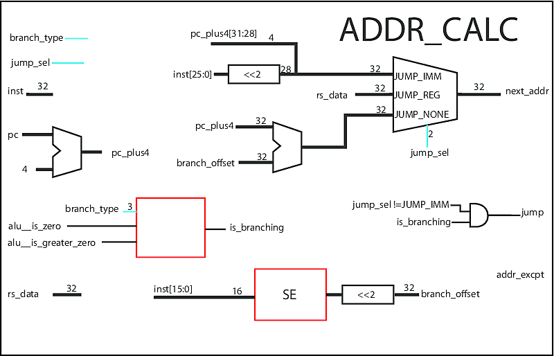
Address Calculator
The address calculator determines what the value of the program counter should be next, based on the current address, type of branch, and branch offset. It uses the ALU to determine if it's a branch or not. The result is sent to the Fetch stage so the correct instruction is fetched next.
////
//// calculate_next_address: Find the proper next address given a target and the PC
////
module calculate_next_address(// Outputs
                              next_addr, is_non_sequential, addr_excpt,
                              // Inputs
                              pc, coprocessor_data, alu__is_zero, alu__is_greater_zero, jump_sel, branch_type, rs_data, inst);


  // Outputs
  output reg  [31:0]  next_addr;         // The final jump address
  output reg          is_non_sequential; // True if we branch or jump
  output reg          addr_excpt;        // Asserted if an invalid address to jump to

  // Inputs
  input [31:0]  pc, coprocessor_data;
  input         alu__is_zero;
  input         alu__is_greater_zero;
  input [1:0]   jump_sel;
  input [2:0]   branch_type;
  input [31:0]  rs_data;  // Used for Jump to Register command
  input [31:0]  inst;

  wire  [25:0]  target;
  wire  [31:0]  branch_offset;

  wire [31:0]   pc_plus4;

  // The target field from the instruction
  assign target = inst[25:0];

  // The branch offset from the instruction
  assign branch_offset =  {{14{inst[15]}}, inst[15:0], 2'b00};

  assign pc_plus4 = pc + 4;

  always @ (*) begin

    // Assume it will be sequential
    next_addr = pc_plus4 + branch_offset;
    is_non_sequential = 0;

    // We are jumping to EPC
    if(jump_sel == `JUMP_EPC) begin
      next_addr = coprocessor_data;
      is_non_sequential = 1;
    end

    // Jump based on target (immediate from instruction)
    if(jump_sel == `JUMP_IMM) begin
      next_addr = {pc_plus4[31:28], (target << 2)};
      is_non_sequential = 1;
    end

    // Jump based on register
    else if(jump_sel == `JUMP_REG) begin
      next_addr = rs_data;
      is_non_sequential = 1;
    end

    // We may be branching
    else begin
      case(branch_type)
        `BRC_EQ: begin
          if( alu__is_zero ) begin
            is_non_sequential = 1;
          end
        end
        `BRC_NEQ: begin
          if( ~alu__is_zero ) begin
            is_non_sequential = 1;
          end
        end

        // In these cases, next_addr = offset << 2
        `BRC_GTZ: begin
          if(alu__is_greater_zero && ~alu__is_zero) begin
            is_non_sequential = 1;
          end
        end
        `BRC_GEZ: begin
          if( (alu__is_greater_zero || alu__is_zero) ) begin
            is_non_sequential = 1;
          end
        end
        `BRC_LTZ: begin
          if(~alu__is_greater_zero && ~alu__is_zero) begin
            is_non_sequential = 1;
          end
        end
        `BRC_LEZ: begin
          if( (~alu__is_greater_zero || alu__is_zero) ) begin
            is_non_sequential = 1;
          end
        end

        // No branch!
        default: is_non_sequential = 0;
      endcase
    end

    // We don't actually use this address exception
    // anymore, so force it to zero
    addr_excpt = 0;
  end
endmodule
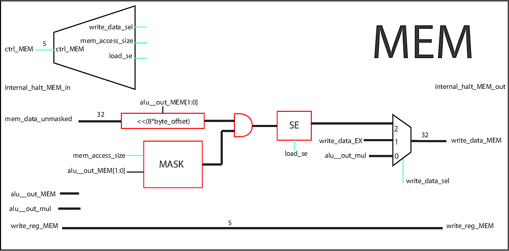
Memory Stage
The memory stage (source) simply reads and writes values to memory. Only a small amount of data can be held in the register file, so most data is stored in memory (RAM). This stage is directly connected to RAM, and masks reads so that the appropriate bytes are sent to the writeback stage.
Virtual Memory and TLB
One of the most important abstractions in computing is virtual memory, which maps the physical addresses of memory to a linear array of addresses in software. This allows programs to assume that they are the only ones using memory, improves security, and sometimes lets programs use more memory than the system physically has via paging. This processor supports virtual memory, translating addresses in the MIPS core.
The mapping between virtual and physical addresses is done with a page table. However, going through memory to translate every address is inefficient and not practical. Therefore, a cache called a Translation Lookaside Buffer (TLB) is used to speed up the process. This cache returns the translation immediately, or if it's not found, raises a TLB miss exception. It's the same as other exceptions, except it goes to a different handler, which is tasked with loading the TLB with the translation from the page table.
////
//// tlb_interface: Module that the core will use to interface with the TLB
////
module tlb_interface(// Outputs
                     output reg [31:0] inst_physical_address, mem_physical_address,
                     output reg        inst_translation_miss, mem_translation_miss, mem_is_writable,
                     // Inputs
                     input [31:0]      inst_virtual_address, mem_virtual_address,
                     input [4:0]       writeIndex,
                     input [31:0]      writeTag, writeData,
                     input             writeEnable, clk, rst_b);

  // These contian the PFN's
  wire [31:0] inst_tlb_data, mem_tlb_data;
  wire        inst_hit, mem_hit;

  // Crete the TLB itself
  mips_tlb  TLB_Memory(// Outputs
                       .readData_1(inst_tlb_data),
                       .readData_2(mem_tlb_data),
                       .hit_1(inst_hit),
                       .hit_2(mem_hit),
                       // Inputs
                       .readTag_1(inst_virtual_address),
                       .readTag_2(mem_virtual_address),
                       .writeIndex(writeIndex),
                       .writeTag(writeTag),
                       .writeData(writeData),
                       .writeEnable(writeEnable),
                       .clk(clk),
                       .rst_b(rst_b));

  // Logic to differentiate between unmapped and mapped address locations
  always @ (*) begin

    // Assume we are not accessing the TLB, therefore not missing
    inst_translation_miss = 0;
    mem_translation_miss  = 0;
    mem_is_writable       = 1;

    // If instuction memory is unmapped, just pass
    // it through after removing the offsets
    if( (inst_virtual_address >= `KSEG0_START) &&
      (inst_virtual_address <= `KSEG0_END)) begin
      inst_physical_address = (inst_virtual_address - `KSEG0_START);
    end
    else if( (inst_virtual_address >= `KSEG1_START) &&
         (inst_virtual_address <= `KSEG1_END)) begin
      inst_physical_address = (inst_virtual_address - `KSEG1_START);
    end
    else begin

      // The physical address is the PFN plus the offset from the virtual
      // address (last 12 bits)
      inst_physical_address = { inst_tlb_data[31:12], inst_virtual_address[11:0] };

      // If we miss, while we are actually accessing the TLB assert that we missed
      inst_translation_miss = ~inst_hit;
    end

    // If mem memory is unmapped, just pass it through
    if( (mem_virtual_address >= `KSEG0_START) &&
      (mem_virtual_address <= `KSEG0_END)) begin
      mem_physical_address = (mem_virtual_address - `KSEG0_START);
    end
    else if( (mem_virtual_address >= `KSEG1_START) &&
         (mem_virtual_address <= `KSEG1_END)) begin
      mem_physical_address = (mem_virtual_address - `KSEG1_START);
    end
    else begin

      // The physical address is the PFN plus the offset from the virtual
      // address (last 12 bits)
      mem_physical_address = { mem_tlb_data[31:12], mem_virtual_address[11:0] };

      // If we miss, while we are actually accessing the TLB assert that we missed
      mem_translation_miss  = ~mem_hit;

      // It is writable only if the D bit is asserted,
      // and we've accessed the TLB
      mem_is_writable = mem_tlb_data[10];
    end
  end
endmodule

// This is the actual TLB memory
module mips_tlb(// Outputs
                output reg [31:0] readData_1, readData_2,
                output reg        hit_1, hit_2,
                // Inputs
                input [31:0]      readTag_1, readTag_2,
                input [4:0]       writeIndex,
                input [31:0]      writeTag, writeData,
                input             writeEnable, clk, rst_b);


  // Define our two data elements for the cache
  reg [31:0] tag [0:31];
  reg [31:0] data [0:31];
  integer i;
  integer j;

  // This resets both the tag and data if rst_b is 0
  // Otherwise, if we have enable asserted
  // then write both the tag and data
  always @ (posedge clk) begin
    if (rst_b == 1'b0) begin
      for(i = 0; i < 32; i = i+1) begin
        tag[i]  <= 32'b0;
        data[i] <= 32'b0;
      end
    end
    else if (writeEnable) begin
      tag[writeIndex]  <= writeTag;
      data[writeIndex] <= writeData;
    end
  end

  // Reading the TLB, we will return the data but it is only valid
  // if the tag matches and we assert hit
  always @(readTag_1, readTag_2) begin

    // We assume no hit
    hit_1 = 1'b0;
    hit_2 = 1'b0;

    // Don't care if hit is zero
    readData_1 = 32'hxxxx_xxxx;
    readData_2 = 32'hxxxx_xxxx;

    // If a tag matches what we are looking for AND its valid
    // bit is set then set hit and output the proper data
    for(j = 0; j < 32; j = j+1) begin

      // Only care if the first 20 bits match, as the other info is useless
      if ( (tag[j][31:12] == readTag_1[31:12]) && data[j][9] ) begin
        readData_1 = data[j];
        hit_1 = 1'b1;
      end
      if ( (tag[j][31:12] == readTag_2[31:12]) && data[j][9]) begin
        readData_2 = data[j];
        hit_2 = 1'b1;
      end
    end
  end
endmodule

// Simple counter that counts to 4
module fourBitCounter(// Outputs
                      output [3:0] count,
                      // Inputs
                      input clk, rst_b);

  reg [3:0] CS, NS;
  assign count = CS;

  // Unless we hit the max, our current state is just an increment
  always @(*) begin
    case(CS)
      4'b1111: NS = 4'b0000;
      default: NS = CS + 1;
    endcase
  end

  // On reset go to state 0, otherwise current state gets next state
  always @(posedge clk) begin
    if (rst_b == 1'b0) begin
      CS <= 4'b0000;
    end
    else begin
      CS <= NS;
    end
  end
endmodule
Kernel - Software
You can't do anything useful with a processor without a program to run, and a useful program to start with is a kernel. The kernel I wrote in assembly is very simple. It supports exception handling and basic virtual memory management, along with system calls and a user/kernel mode. While basic, without these features, the processor would not work as expected.
Exception Handler
The bulk of the kernel is the exception handling logic, which reads the cause of the exception and acts accordingly. It determines the cause of the exception, resolves it (or halts if it cannot), and returns control to the main program with an ERET instruction. Because there are no functions in assembly and the exception handler may be invoked numerous times, we create a simple stack in memory to handle recursive system calls.
# Our small stub kernel
.ktext
  # Set up stack space - address 90000000 will be the "stack" pointer always
  lui $k1, 0x90000000
  sw $k1, 0($k1)

  # Jump to the user program with an ERET instruction
  lui $4, 0x00400000
  mtc0 $4, $14
  .word 0x42000018

# Exception Handler Code
.ktext 0x80000180
  # Get the cause code
  # $k0 == cause code

  mfc0 $k0, $13

  # System Call Exception
  addi $k1, $zero, 32
  beq $k0, $k1, systemCall

  # AdEL or AdES Exception
  addi $k1, $zero, 16
  beq $k0, $k1, AdE

  addi $k1, $zero, 20
  beq $k0, $k1, AdE

  # It must be another type of exception
  beq $zero, $zero, otherExceptions

systemCall:
  # Branch based on the value of v0
  addi $k1, $zero, 0xA
  beq $v0, $k1, vZeroA

  addi $k1, $zero, 0x20
  beq $v0, $k1, vZero20

  addi $k1, $zero, 0x21
  beq $v0, $k1, vZero21

  # It must be another type of syscall
  beq $zero, $zero, otherExceptions

vZeroA:
  # Halt with TESTDONE instruction
  .word 0xE

vZero20:
  # $k0 == EPC
  mfc0 $k0, $14

  # EPC += 4
  addi $k0, $k0, 4
  mtc0 $k0, $14

  # Store the value of v1 in memory
  lui $k1, 0x90000000

  # $k0 ==  "stack" pointer
  lw $k0, 0($k1)
  # Increment
  addi $k0, $k0, 4

  # Store v1, and restore SP into 90000000
  sw $v1, 0($k0)

  sw $k0, 0($k1)

  # Return with ERET
  .word 0x42000018

vZero21:
  # $k0 == EPC
  mfc0 $k0, $14

  # EPC += 4
  addi $k0, $k0, 4
  mtc0 $k0, $14

  # Load the value of "stack" into a0
  lui $k1, 0x90000000

  # $k0 == "stack" pointer
  lw $k0, 0($k1)

  # Load a0
  lw $a0, 0($k0)

  # Decrement stack pointer
  addi $k0, $k0, -4

  # Restore into memory
  sw $k0, 0($k1)

  # Return with ERET
  .word 0x42000018

AdE:
  # $k0 == EPC
  mfc0 $k0, $14

  # EPC += 4
  addi $k0, $k0, 4
  mtc0 $k0, $14

  # Return with ERET
  .word 0x42000018

otherExceptions:
  # cause code is in k0

  # Put 0xDEADC0DE in k1
  addi $k1, $zero, 0
  lui $k1, 0xDEAD
  addi $k1, $k1, 0xC0DE

  # Halt with TESTDONE instruction
  .word 0xE

# User level Code
.text
  # Done
  addi $v0, $zero, 0xa
  syscall
TLB Exception Handler
The TLB is managed through software and the code below is the TLB handler along with a simple test case. When a TLB exception occurs, instead of being sent to the general exception handler, control is sent here. We're then able to read the page table (which is hardcoded in this case), and load the TLB with the appropriate values. Once completed, it returns with an ERET instruction and the processor executes the faulting instruction again. This time without a TLB miss.
# This tests if we can jump and execute
# simple instructions with the TLB
.ktext

  # Change Index
  li $4, 0x11
  mtc0 $4, $0

  # Change EntryHi (Tag / Virtual Address)
  li $4, 0x40009000
  mtc0 $4, $10

  # Change EntryLo (Data / Physical Address)
  li $4, 0x00000700
  mtc0 $4, $2

  # tlbwi
  .word 0x42000002

  # ERET to user space
  li $4, 0x40009000
  mtc0 $4, $14
  .word 0x42000018

# General Exception Handler
.ktext 0x80000180
  li $5, 0xc0070002
  .word 0xE

  li $10, 0xFa17Fa17
  .word 0xE
  li $10, 0xFa17Fa17

# TLB Exception Handler
# Find the hashed page table address
.ktext 0x80000200
  # Calculate hashed page table addr
  # Base + {VPN[7:0], 3'b000} == base + (badVaddr[19:12] << 3)
  # K0 = BadVAddr

  mfc0 $k0, $8
  li $k1, 0x000ff000
  and $k0, $k0, $k1

  # K0 = {VPN[7:0], 3'b000}
  srl $k0, $k0, 9

  # Base = 0xA000_3000
  li $k1, 0xA0003000
  add $k0, $k0, $k1

  # store the page table entry in the TLB
  # (ASSUMING NOT A PAGE FAULT)
  # Get Data
  lw $k1, 0($k0)
  mtc0 $k1, $2

  # Get Tag
  lw $k1, 4($k0)
  mtc0 $k1, $10

  # tlbwr
  .word 0x42000006

  # Return and Retry the instruction with an ERET
  .word 0x42000018

# Page Table
.kdata
  # Data (not used)
  .word 0x00001700
  # Tag (not used)
  .word 0x40000000

  # Data (not used)
  .word 0x00001700
  # Tag (not used)
  .word 0x50001000

  # Data
  .word 0x00001700
  # Tag
  .word 0x50002000

# This is Virtual Address 0x4000_0000
.text
  # TLB Entry does not exist, miss handle
  li $9, 0x40000004
  lw $10, 0($9)

  li $9, 0x50001010
  lw $11, 0($9)

  li $9, 0x5000201C
  lw $12, 0($9)

  .word 0xE

.data
  .word 0xfa17fa17
  .word 0x13371337
  .word 0xfa17fa17
  .word 0xfa17fa17
  .word 0x13371338
  .word 0xfa17fa17
  .word 0xfa17fa17
  .word 0x13371339
  .word 0xfa17fa17